[Page 2]
These 2 image acquisitions have been taken 1 minute apart in this same patient. The one on the left (Figure 1) reproduces the LV geometry obtained at the previous outpatient examination, the one on the right (Figure 2) is obtained by optimizing LV geometry. What do we mean by optimizing LV geometry ? By this, we intend to acquire the maximum possible LV long axis (there is only 1 possible maximum – and thus true – LV l long axis). How can we achieve this ?
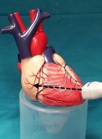
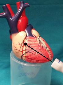
Figure 3 shows the transducer position which corresponds to the image in Figure 1, whereas Figure 4 shows the transducer position which corresponds to the image in Figure 2. In Figure 4, the transducer is positioned correctly on the true LV apex and is thus the maximum long axis of the LV geometric ellipsoid. In Figure 3, the transducer is incorrectly placed on the apical anterior wall, producing a “foreshortening” of the LV cavity (shorter LV long axis compared to the optimal maximum LV long axis).